


Estimated reading time: 5 minutes
Table of contents
- Radar Speckle: The “Salt and Pepper” Effect
- Multi-Look Processing: Reducing Noise by Averaging Data
- Spatial Filtering: Smoothing the Image with a Moving Window
- Slant-Range Distortion: Misrepresentation of Object Sizes
- Antenna Pattern Effects: Variations in Brightness
- Radiometric Resolution and Dynamic Range
- Radar Image Calibration: Ensuring Accuracy
- Also Read
Radar imaging plays a crucial role in remote sensing, offering valuable data for various applications such as weather forecasting, environmental monitoring, and military reconnaissance. However, understanding the properties of radar images is essential for accurate interpretation and analysis. In this article, we will explore the key properties of radar images, including speckle, slant-range distortion, antenna pattern effects, and calibration, while providing real-world examples to clarify these concepts.
Radar Speckle: The “Salt and Pepper” Effect
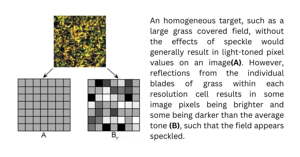
One of the most common characteristics of radar images is radar speckle, which appears as a grainy “salt and pepper” texture. Speckle occurs due to random constructive and destructive interference from multiple scattering returns within each resolution cell. This phenomenon can make an image look noisy and difficult to interpret.
Example:
Imagine looking at a calm pond on a clear day; the reflection of the surroundings is smooth and well-defined. However, if a light drizzle begins, tiny ripples form on the water surface, causing the reflections to appear distorted and scattered. Similarly, in radar imaging, individual objects such as blades of grass, tree leaves, or even ocean waves contribute to speckle, making the image appear rough or speckled.
To minimize speckle and improve image clarity, two primary techniques are used:
- Multi-look processing
- Spatial filtering
Multi-Look Processing: Reducing Noise by Averaging Data
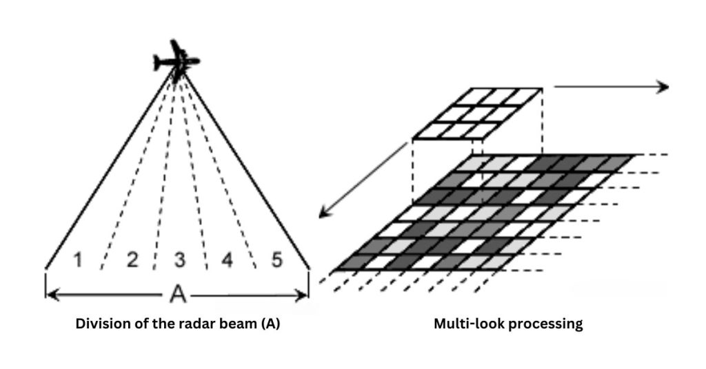
Multi-look processing involves dividing the radar beam into multiple sub-beams, each capturing an independent “look” at the target area. By averaging these multiple looks, the amount of speckle is reduced, leading to a smoother and clearer final image.
Example:
Consider taking five different photos of a busy street from slightly different angles. Each image may contain noise, such as moving cars or pedestrians in different positions. However, if you overlay and average these images, you will get a more stable and consistent view of the scene. This is how multi-look processing works in radar imaging to reduce unwanted noise.
Spatial Filtering: Smoothing the Image with a Moving Window
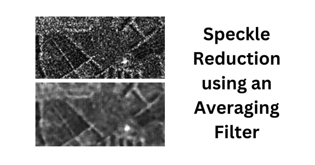
Spatial filtering is another method to reduce speckle by applying a mathematical operation to a small group of pixels (e.g., 3×3 or 5×5 windows). The process involves moving this window across the image and replacing the central pixel with the average or median value of the surrounding pixels, creating a smoothing effect.
Example:
Think of a pixelated digital photo taken in low light. By applying a filter (like the blur function in photo editing apps), the sharp pixelation is reduced, and the overall image appears smoother. In radar images, spatial filtering performs a similar function, making features more distinguishable.
Slant-Range Distortion: Misrepresentation of Object Sizes
Slant-range distortion occurs because radar measures distances in slant range rather than ground range. This means that objects closer to the radar sensor appear compressed, while objects farther away appear stretched. For accurate measurements, the image must be converted to ground-range format.
Example:
Imagine taking a photo of a tall building from the ground. The top of the building appears much smaller compared to the bottom, even though in reality, both sections are of equal width. Similarly, radar images require correction to accurately represent distances.
Antenna Pattern Effects: Variations in Brightness
Radar antennas transmit more power in the mid-range portion of the swath than at the near and far ranges. This leads to a variation in brightness across the image, with the central portion appearing stronger than the edges. To correct this effect, an antenna pattern correction is applied.
Example:
Picture a flashlight beam directed at a wall. The center of the beam is bright, while the edges gradually fade. Similarly, in radar images, variations in brightness must be corrected to ensure uniformity.
Radiometric Resolution and Dynamic Range
The ability of a remote sensing system to differentiate between different brightness levels is known as radiometric resolution. While optical sensors like those on Landsat satellites typically provide 256 intensity levels, radar systems can distinguish up to 100,000 levels. However, since human eyes can only perceive about 40 intensity levels at a time, radar data is usually scaled down to 256 levels for easier interpretation.
Example:
Consider adjusting the brightness of your phone screen. If the screen supports a higher number of brightness levels, the transition between different brightness settings will be smoother. Similarly, higher radiometric resolution in radar imagery allows for better differentiation of features.
Radar Image Calibration: Ensuring Accuracy
Calibration is crucial for ensuring that radar data remains consistent and accurate over time. Two types of calibration are used:
- Relative Calibration – Corrects variations within an image and ensures uniformity.
- Absolute Calibration – Compares radar data to actual ground measurements for precise analysis.
Example:
Think about weighing yourself on a scale. If the scale is slightly off, you may get different readings each time. Calibration, in this case, would mean adjusting the scale using a known weight to ensure accurate measurements. Similarly, radar images must be calibrated to provide meaningful data for scientific analysis.
Conclusion
Radar imaging is a powerful tool, but its effectiveness depends on understanding and correcting for various properties like speckle, slant-range distortion, and antenna pattern effects. Through techniques like multi-look processing, spatial filtering, and calibration, radar images can be optimized for applications in environmental monitoring, agriculture, disaster management, and defense. By relating these concepts to everyday experiences, we can better appreciate the role of radar in our modern world.


