


Radar remote sensing is a powerful technology used for Earth observation, topographic mapping, and environmental monitoring. However, like all remote sensing systems, radar images are prone to geometric distortions. These distortions arise primarily due to radar’s side-looking viewing geometry and its fundamental characteristic of measuring distances in slant-range rather than ground-range. Understanding these distortions is crucial for accurate image interpretation and analysis. In this blog, we will explore the key types of Radar Image Distortions, their causes, and possible correction techniques.
To understand these distortions better, think of using a flashlight in a dark room. If you point it straight down, the light covers a small, well-defined area. But if you tilt the flashlight at an angle, the beam stretches across the floor, making objects appear distorted. Radar imaging works in a similar way, where the angle at which the radar beam strikes the surface influences how features appear in the final image.

1. Slant-Range Scale Distortion
One of the most fundamental distortions in radar imagery is slant-range scale distortion. This occurs because radar measures distances to objects in slant-range, rather than their actual horizontal ground distance. As a result:
- Objects in the near range appear compressed, while those in the far range appear stretched.
- Two objects of the same size on the ground (A1 and B1) may have different apparent sizes in slant-range (A2 and B2).
Real-Life Example:
Imagine you are looking at a row of houses through a wide-angle camera lens. The houses closer to you appear much larger than the ones farther away, even though all the houses are of the same size in reality. Similarly, radar images create distortions where nearby objects appear smaller or larger than they actually are, depending on their position in the image.
Correction:
To correct this distortion, trigonometric calculations are used to convert slant-range measurements into ground-range distances. The corrected image ensures that objects are displayed in their true proportions. This is similar to adjusting the perspective of a wide-angle photo using software so that all objects appear in their correct scale.
2. Relief Displacement and Geometric Distortions
Radar images, like optical images, experience distortions due to relief displacement. However, in radar images, this displacement differs because it is one-dimensional and occurs perpendicular to the flight path. The displacement is also reversed, meaning features are displaced towards the radar sensor instead of away.
The two major distortions caused by relief displacement are foreshortening and layover.
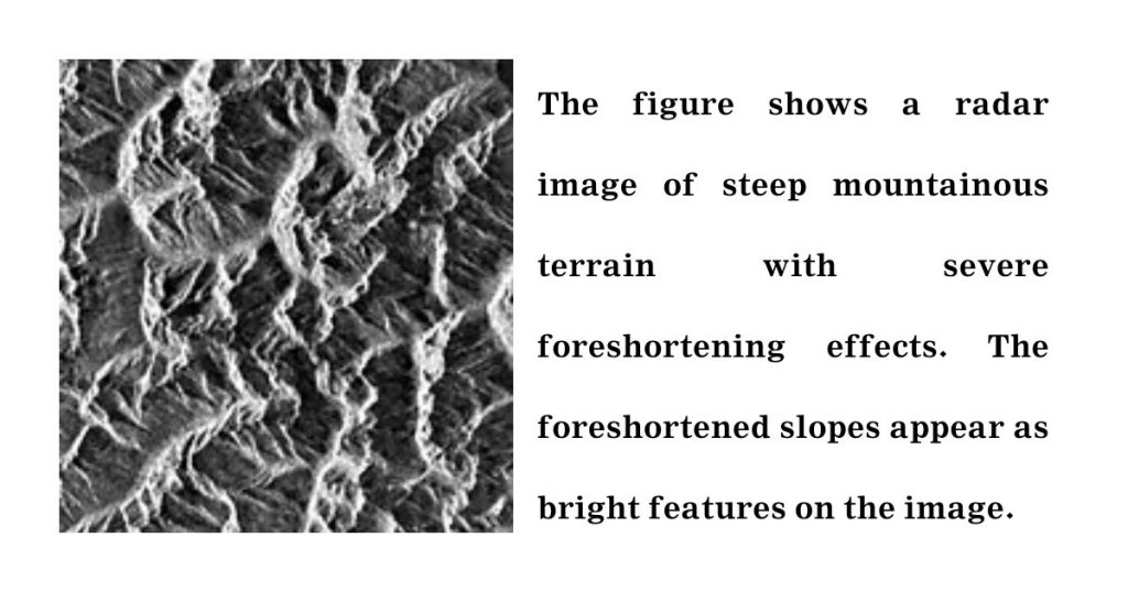
2.1 Foreshortening
Foreshortening occurs when the radar beam reaches the base of a tilted feature before it reaches the top. This causes the slope of the feature to appear compressed in the radar image.
- If the slope is perpendicular to the radar beam, foreshortening is at its maximum, reducing the slope to an effective length of zero.
- Foreshortened slopes appear as bright features in the radar image.
Real-Life Example:
Think about looking at a tall building from an airplane. The lower floors of the building might appear squashed or barely visible, while the upper floors seem prominent. This happens because of the angle at which you are viewing the building, similar to how radar foreshortening affects mountainous terrain in images.
Correction:
Foreshortening can be reduced by selecting radar incidence angles carefully and using stereo radar pairs to derive elevation models. This technique is similar to how architects use multiple 3D models from different perspectives to get the most accurate representation of a building.
2.2 Layover
Layover occurs when the radar beam reaches the top of a tall feature (B) before reaching its base (A). This causes the top to be displaced toward the radar sensor, effectively “laying over” the base (B’ to A’).
- Layover is most severe at small incidence angles and in mountainous terrain.
- The effect of layover appears similar to foreshortening, but in this case, the object is completely distorted, making interpretation challenging.
Image on the right side illustrates radar shadow effects on the right side of the hillsides which are being illuminated from the left.

Real-Life Example:
Imagine taking a selfie with a smartphone while holding it at a low angle. Your forehead may look disproportionately large, and your chin may seem smaller than usual. This exaggerated perspective is similar to layover distortion in radar images, where the top of an object appears much closer than the base.
Correction:
Layover is difficult to correct, but multiple radar images from different angles can help identify and mitigate its effects. This is similar to taking photos from multiple angles to avoid distortions in photography.
3. Radar Shadow
Radar shadow occurs when the radar beam is unable to illuminate certain areas due to steep terrain or vertical structures.
- Areas behind steep slopes remain unilluminated and appear as dark shadows in the image.
- The effect increases with the incidence angle, as the radar looks more obliquely at the surface.

Real-Life Example:
Picture standing near a bright lamp post at night. If you place a tall object in front of it, a dark shadow forms behind it where no light reaches. Similarly, in radar images, steep mountains or buildings can block radar signals, creating dark areas known as radar shadows.

Correction:
Radar shadow is difficult to correct, but using multi-angle radar imaging or complementary optical images can help in interpretation. This is similar to using multiple light sources in photography to reduce harsh shadows and enhance visibility.
Conclusion
Understanding and correcting Radar Image Distortions is essential for accurate remote sensing analysis. The primary distortions include:
- Slant-range scale distortion (corrected using trigonometric conversions).
- Foreshortening (managed through careful selection of incidence angles and stereo imaging).
- Layover (challenging to correct but mitigated with multi-angle imaging).
- Radar shadow (identified and analyzed using complementary data sources).
By employing advanced processing techniques and combining data from multiple sources, we can enhance the accuracy of radar imagery for applications in geospatial analysis, topographic mapping, and disaster management. Just as photographers adjust angles, lighting, and lenses to capture the perfect shot, radar analysts must account for these distortions to achieve the most accurate images possible.